
This article aims at reading data from the MPU9250. It only covers how to get the raw data from the MPU9250. I'd like to post another article about how to calibrate the MPU9250.
In this article, we will use the I2C library mentioned in this article. The datasheet and register map for the MPU9250 can be downloaded here.
The example code can be downloaded from GitHub. The example code uses the interrupt of the Arduino and I haven't talked about the interrupt in this article cause it'a a another story. If you are interested in the time interrupt function of the Arduino, please let me know.
A brief introduction to the MPU9250
The MPU9250 contains a die that houses the 3-Axis gyroscope and the 3-Axis accelerometer with a AK8963 3-Axis magnetometer from Asahi Kasei Microdevices Corporation. The device works at a VDD range from 2.4V to 3.6V.
The I²C Module of the MPU9250 supports up to 400kHz clock frequency and it always acts as a slave to the Arduino. It also contains an auxiliary I2C master interface to talk to the external 3rd party sensor (AK8963).
The MPU9250 has three 16-bit outputs gyroscope, accelerometer and magnetometer. The gyroscope module and accelerometer module feature a user-programmable full-scale range of 


The MPU9250 comes with a digital low-pass filter for the gyroscope and accelerometer.
MPU9250 I²C communication
The I²C Module of the MPU9250 has Single-Byte sequence mode and Burst Sequence mode. The protocol to write to it is:
 

Table 1 Writing to MPU9250, taken from MPU-9250 Product Specification Revision 1.0
The protocol to read from it is:
 

Table 2 Reading from MPU9250, taken from MPU-9250 Product Specification Revision 1.0
Where
- S – START signal
- AD – address bits
- W – WRITE
- R – READ
- ACK – acknowledge bit
- RA – register address
- DATA – data package
- P – STOP signal
- NACK – not acknowledge bit
Refer to this post for more detail.
Interpret the raw data
 

Table 3 Gyroscope Specifications, taken from MPU-9250 Register Map and Descriptions Revision 1.6
 

Table 4 Accelerometer Specifications, taken from MPU-9250 Register Map and Descriptions Revision 1.6
 

Table 5 Magnetometer measurement data format, taken from the AK8963 Datasheet
The table above shows the sensitivity scale factor, different full-scale range has different sensitivity scale factor. The raw data of the MPU9250 is 16-bit long, which leads to a range from -32768 to 32767 (

The sensitivity scale factor for the magnetometer is fix to 

MPU9250 setup
Clock source
Let's take a look at the register 107(PWR_MGMT_1):
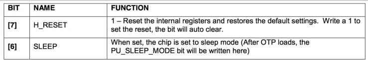 

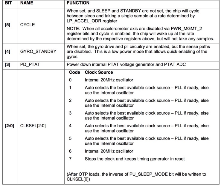 

Table 6 Power management register, taken from MPU-9250 Register Map and Descriptions Revision 1.6
The MPU9250 allows different clock source:
- The internal 20MHz oscillator
- The X, Y or Z axis of the gyroscope.
The internal oscillator consumes less power and the axis of the gyroscope leads to a more accurate clock source. For example, the accuracy of the measurement is more important, we could tie the clock source to one of the axes of the gyroscope:
    #define MPU9250_AD 0x68
    #define PWR_MGMT_1_AD 0x6B

    startTrans(MPU9250_AD);
    write(PWR_MGMT_1_AD);
    write(0x01,true); //0000 0001 in binary, set the clock reference to X axis gyroscope to get a better accuracy
Gyroscope and accelerometer setup
The gyroscope is controlled by the register 27(GYRO_CONFIG):
 

Table 7 Gyroscope specification, taken from MPU-9250 Register Map and Descriptions Revision 1.6
The accelerometer is controlled by the register 28(ACCEL_CONFIG_1) and 29(ACCEL_CONFIG_2):
 

Table 8 Register 28, taken from MPU-9250 Register Map and Descriptions Revision 1.6
 

Table 9 Register 29, taken from MPU-9250 Register Map and Descriptions Revision 1.6
We could set the full-scale range and the internal digital low-pass filter (DLPF) of the gyroscope and the accelerometer. The DLPF of the gyroscope is configured by the bit 2 to bit 0 of the register 26(CONFIG):
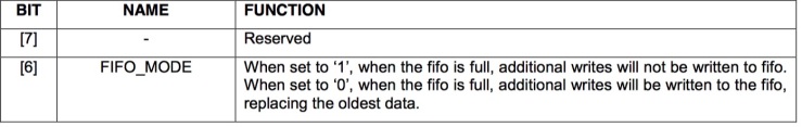 

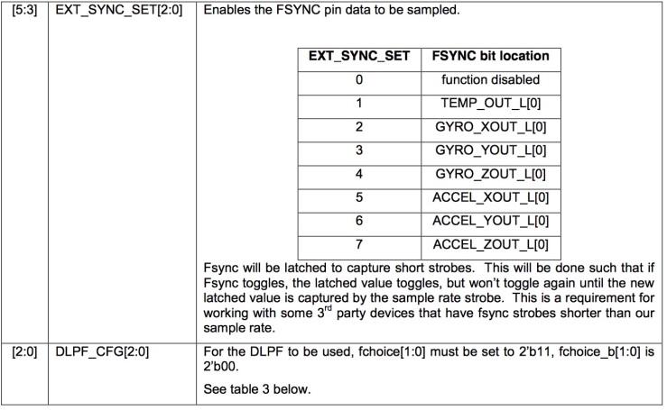 

Table 10 Register 26, taken from MPU-9250 Register Map and Descriptions Revision 1.6
The tables below show the how to set the bandwidth of the DLPF for the gyroscope and the accelerometer (the FCHOICE in table 11 and ACCEL_FCHOICE in the table 12 are the inverted value of Fchoice_b in the register 27 and accel_fchoice_b in the register 29):
 

Table 11 DLPF of the gyroscope, taken from MPU-9250 Register Map and Descriptions Revision 1.6
 

Table 12 DLPF of the accelerometer, taken from MPU-9250 Register Map and Descriptions Revision 1.6
As mentioned above, we need to specify the full-scale range of the gyroscope and the accelerometer. This can be done by setting the bit 4 to bit 3 in register 27 and register 28 to different values based on the full-scale range you want to use.
Usually, the smaller bandwidth the DLPF has, the less noise it will contain. However, a smaller bandwidth also leads to a slower response, which means the data converges to the true value slowly. The table 11 and 12 give the delay of each bandwidth, we should choose the bandwidth based on the situation. Please note that enabling the DLPF makes the output rate of the gyroscope and the accelerometer drop to 1kHz (The gyroscope is initialized to 8kHz and the accelerometer is initialized to 4kHz).
    #define GYRO_CONFIG_AD 0x1B
    #define ACCEL_CONFIG_1_AD 0x1C
    #define ACCEL_CONFIG_2_AD 0x1D
    #define CONFIG_AD 0x1A

    startTrans(MPU9250_AD);
    write(ACCEL_CONFIG_1_AD);
    write(0x08,true); //0000 1000 in binary. Set the accel scale to 4g

    startTrans(MPU9250_AD);
    write(GYRO_CONFIG_AD);
    write(0x08,true); //0000 1000 in binary. Set the gyro scale to 500 °/s and FCHOICE_B

    startTrans(MPU9250_AD);
    write(ACCEL_CONFIG_2_AD);
    write(0x05,true);  //0000 0101 in binary. Turn on the internal low-pass filter for accelerometer with 10.2Hz bandwidth

    startTrans(MPU9250_AD);
    write(CONFIG_AD);
    write(0x05,true);//0000 0101 in binary. Turn on the internal low-pass filter for gyroscope with 10Hz bandwidth
Magnetometer setup
The magnetometer setup is a little bit complex than the gyroscope and the accelerometer.
 

Figure 1 Block diagram of the I2C interface, taken from MPU-9250 Product Specification Revision 1.0
The auxiliary I2C master interface of the MPU9250 contains an interface bypass multiplexer, which allows the system processor program the 3rd party sensor.
The bypass multiplexer is controlled by the register 55 (INT Pin / Bypass Enable Configuration):
 

Table 13 Register 55, taken from MPU-9250 Register Map and Descriptions Revision 1.6
To turn on the bypass multiplexer of the I2C master interface, we need to disable the I2C master interface first. The I2C master interface is controlled in the register 106 (User Control):
 

Table 14 Register 106, taken from MPU-9250 Register Map and Descriptions Revision 1.6
We need to write 0 to the I2C_MST_EN bit to disable the I2C master interface and write 1 to the BYPASS_EN bit to turn on the bypass multiplexer.
    #define USER_CTRL_AD 0x6A
    #define INT_BYPASS_CONFIG_AD 0x37

    // Actually we don't need this step cause the reset value of the register 106 is 0x00
    startTrans(MPU9250_AD);
    write(USER_CTRL_AD);
    write(0x00,true);

    startTrans(MPU9250_AD);
    write(INT_BYPASS_CONFIG_AD);
    write(0x02,true);   //0000 0010 in binary, turn on the bypass multiplexer
The AK8963 has a read-only Fuse ROM Access mode that allows the access to the Fuse ROM data. The Fuse ROM contains the sensitivity adjustment data for each axis. The Control 1 register of the AK8963 controls the operation mode:
 

Table 15 Control 1 register, taken from MPU-9250 Register Map and Descriptions Revision 1.6
The operation mode is configured by the bit 3 to bit 0 (other code settings are prohibited). The bit 4 of this register controls the output bit, "0" is 14-bit output and "1" is 16-bit output. Note that we has to wait for some time to let the mode change complete.:
- "0000" – Power-down mode
- "0001" – Single measurement mode
- "0010" – Continuous measurement mode 1 (Sensor is measured at 8Hz)
- "0110" – Continuous measurement mode 2 (Sensor is measured at 100Hz)
- "0100" – External trigger measurement mode
- "1000" – Self-test mode
- "1111" – Fuse ROM access mode
    #define CNTL1_AD 0x0A   //control 1 register address

    // setup the Magnetometer to fuse ROM access mode to get the Sensitivity Adjustment values and 16-bit output
    startTrans(MAG_AD);
    write(CNTL1_AD);
    write(0x1F,true);  //0001 1111 in binary

    delay(100);  //wait for the mode changes
After setting the AK8963 to the Fuse ROM Access mode, we need to read from the Fuse ROM: ASAX (Magnetic sensor X-axis sensitivity adjustment value), ASAY (Magnetic sensor Y-axis sensitivity adjustment value) and ASAZ (Magnetic sensor Z-axis sensitivity adjustment value) register. The formula to adjust the sensitivity is
Formula taken from MPU-9250 Register Map and Descriptions Revision 1.6
Where:

- H – output data
- ASA – sensitivity adjustment value
- Hadj – adjusted measurement data
    #define ASAX_AD 0x10

    //read the Sensitivit Adjustment values
    startTrans(MAG_AD);
    write(ASAX_AD);
    requestFrom(MAG_AD,3,true);
    asax = (readBuffer()-128)*0.5/128+1;
    asay = (readBuffer()-128)*0.5/128+1;
    asaz = (readBuffer()-128)*0.5/128+1;
Please note that we has to change the chip to power-down mode first then switch it to another mode:
    //reset the Magnetometer to power down mode
    startTrans(MAG_AD);
    write(CNTL1_AD);
    write(0x00,true);

    //wait for the mode changes
    delay(100);
Then we could set the chip to continuous mode 2 and 16-bit output:
    //set the Magnetometer to continuous mode 2(100Hz) and 16-bit output
    startTrans(MAG_AD);
    write(CNTL1_AD);
    write(0x16,true);   //0001 0110 in binary

    //wait for the mode changes
    delay(100);
Read from the MPU9250
The MPU9250 contains a FIFO read write register. Data is written to this register in order of register number (from lowest to highest). The problem is that we have to read the oldest data in the FIFO buffer first which is not we want. For example, we can compute the attitude of the aircraft based on these readings and we want to know the attitude of the aircraft at a specific time. Reading the oldest data first adds a delay in the process. Therefore, we won't use the FIFO buffer.
Register Names ending in _H and _L contain the high and low bytes, respectively, of an internal register value.
This means the accelerometer and the gyroscope measurement registers are made up of two sets of registers: an internal register set and a user-facing read register set. The internal register set is updated at the sample rate and the user-facing register set is updated when the serial interface is idle. This mechanism ensures the data is correct while reading from the user-facing read register and the set of single byte reads correspond to the same sampling instant when the burst read mode is used.
The AK8963 also allows us to read the measurement data registers even in a measurement period.
Read the gyroscope
The latest gyroscope data is stored in the register 67 to 72:
 

Table 16 Gyroscope measurement data registers
To assemble the tow bytes into the correct data, we could shift the high byte to the left 8 bits and or it with the low byte: (highByte<<8) | lowByte.
    #define GYRO_XOUT_H_AD 0x43

    //read the gyro
    startTrans(MPU9250_AD);
    write(GYRO_XOUT_H_AD);
    requestFrom(MPU9250_AD,6,true);
    gyroX = (readBuffer()<<8) | readBuffer();
    gyroY = (readBuffer()<<8) | readBuffer();
    gyroZ = (readBuffer()<<8) | readBuffer();
Read the accelerometer
The latest gyroscope data is stored in the register 59 to 64:
 

Table 17 Accelerometer measurement data registers
    #define ACCEL_XOUT_H_AD 0x3B

    //read the accelerate
    startTrans(MPU9250_AD);
    write(ACCEL_XOUT_H_AD);
    requestFrom(MPU9250_AD,6,true);
    accelX = (readBuffer()<<8) | readBuffer();
    accelY = (readBuffer()<<8) | readBuffer();
    accelZ = (readBuffer()<<8) | readBuffer();
Read the magnetometer
First we need to pull the DRDY bit in the Status 1 register of the AK8963 to check whether the data is ready. "1" means it's ready, "0" means it's not ready.
If the data is ready, we could start reading the measurement data registers. When this process is started, the DRDY bit is set to "0" by hardware automatically.
 

Table 18 Magnetometer measurement data registers
After reading the measurement data registers, the Status 2 register has to be read to inform the AK8963 that the reading is finished. The HOFL bit in the Status 2 register should be check to know whether the magnetic sensor is overflown. "0" is not overflown, "1" means overflown and the data read should be discarded.
    #define DATA_READY_MASK 0x01
    #define MAGIC_OVERFLOW_MASK 0x8

    startTrans(MAG_AD);
    write(STATUS_1_AD);
    requestFrom(MAG_AD,1,true);  //pull the DRDY bit
    if((readBuffer() & DATA_READY) == DATA_READY){
        startTrans(MAG_AD);
        write(HXL_AD);
        requestFrom(MAG_AD,7,true);
        byte* buffer = getBuffer();
        if(!(buffer[6] & MAGIC_OVERFLOW)){     //check whether the magnetic sensor is overflown
          magneX = buffer[0] | (buffer[1]<<8);
          magneY = buffer[2] | (buffer[3]<<8);
          magneZ = buffer[4] | (buffer[5]<<8);
        }
    }
Print the data
Print the data is simple. Just remember to interpret the raw data.
    Serial.print("GYRO_X: ");
    Serial.print(gyroX/GYRO_SENS);
    Serial.print(" GYRO_Y: ");
    Serial.print(gyroY/GYRO_SENS);
    Serial.print(" GYRO_Z: ");
    Serial.print(gyroZ/GYRO_SENS);
    Serial.print(" ACCEL_X: ");
    Serial.print(accelX/ACCEL_SENS);
    Serial.print(" ACCEL_Y: ");
    Serial.print(accelY/ACCEL_SENS);
    Serial.print(" ACCEL_Z: ");
    Serial.print(accelZ/ACCEL_SENS);
    Serial.print(" MAGNE_X: ");
    Serial.print(magneX*asax*SCALE);
    Serial.print(" MAGNE_Y: ");
    Serial.print(magneY*asay*SCALE);
    Serial.print(" MAGNE_Z: ");
    Serial.print(magneZ*asaz*SCALE);

Hello, you mentionned that you could possibly do an article about how to calibrate the MPU 9250, have you ever made it ? I’m currently working with a MPU 9250 and it would have been very useful to me !
LikeLiked by 1 person
Sorry Arthur, I haven’t done that part cuz I have to focus on my job these days. If I get time I will try to work on it.
LikeLike
Hi Arthur, I just published an article about how to calibrate the magnetometer, hope it’s helpful.
LikeLike
Hi Arthur, I have posted it on my new blog(https://xianyu.world/?p=134&lang=en), hope it’s helpful.
LikeLike
Why is “Quaternion” not mentioned here?
LikeLike
Hi, here it’s only about how to get raw data from the sensor.
LikeLike
I have a problem with the code, when I write it in arduino the part of the code
startTrans (MAG_AD);
I always get that is not declared, do I need any library?
LikeLike
Hi, the MAG_AD stands for the pin for Magnetometer, you can check the full example here: https://github.com/Earsuit/I2C/blob/master/examples/MPU9250/MPU9250.ino
LikeLike
Thanks for this topic: “Please note that enabling the DLPF makes the output rate of the gyroscope and the accelerometer drop to 1kHz (The gyroscope is initialized to 8kHz and the accelerometer is initialized to 4kHz).”
in Arduino IDE void setup I write this line: “I2CwriteByte(MPU9250_ADDRESS, 26, 0b00000000);”
Because of this I can disable the filter and reach the 4 kHz sampling frequency with the MPU 9250 accelerometer. Thank you man, you save my project.
LikeLike
Hi, I’m glad it helps 🙂
LikeLike
Very helpful article, helped resolve some issues, even though I was using a PIC rather than an Arduino.
LikeLike
Hello everyone. And how to do it on esp32? I found the code, but something doesn’t want to work …
LikeLike
requestFrom(MAG_AD,1,true); //pull the DRDY bit
I don’t understand how to pull the DRDY, can you explain what is the meaning of pull the DRDY?
LikeLike
Hi, the “pull” here means read the DRDY bit in the Status 1 register of the AK8963 to check whether the data is ready. “1” means it’s ready, “0” means it’s not ready.
LikeLike
Thank you, i almost throw this module in the trash when i falled on your post, now it begin working, the sequence is my problem in developpement…..
LikeLike
Hey man,
For some reason this doesn’t work with the servo library. Do you know how to fix it?
LikeLike
Sorry, could you give more details?
LikeLike